Metal Detector Circuit Design electronic pulse metal detector circuit In the category Metal Detectors more articles and learn more information about Metal Detector Circuit Design electronic pulse metal detector circuit Reviews Price Specifications Features Image manuals videos Accessories All this in metal detectors for gold.

Metal Detector Circuit
Description
Read Also : Simple Bfo Metal Detector Improved Circuit Design


Notes
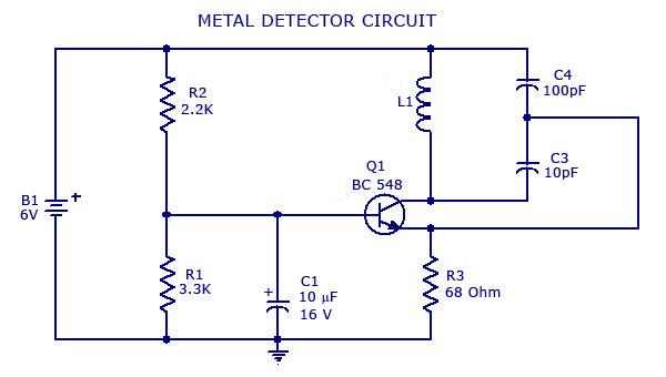
Metal Detector Circuit .
Read Also : Metal detector circuit diagram
metal detector circuit using ic 555


Electronic circuits that use the ic 555 Timer, A simple metal detector electronic project can be designed using a simple 555 timer circuit. As you can see in the schematic circuit, this project requires some external electronic electronic parts. This circuit detects metal and magnets. When a magnet is close the choke 10mH, output frequency…. Read Post
Read Also : Scheme for metal detector How to make a homemade metal detector
Metal detector circuit diagram

Metal detector circuit diagram,The metal detector is a relatively simple device, an electronic circuit that provides good sensitivity and stability. A distinctive feature of this device is the low operating frequency. Metal detector coil operates at a frequency of 3 kHz. It provides, on the one hand, and poor response to unwanted signals… Read Post
Design electronic pulse metal detector circuit

Design electronic pulse metal detector circuit,When established, the head of research of electromagnetic field which extends to the environment. On the surface of the minerals that were in the region to discuss the file, under the influence of the electromagnetic field having what is called eddy currents. These eddy currents create electromagnetic fields against their… Read Post
Pulse Induction Metal Detector Circuit

We often associate great depth and pulse induction metal detector A PI, understand pulse induction metal detector, Pulse repetition rate (frequency of the transmitter ) with a typical pulse induction metal detector is approximately 100 Hz. Different models, Vlf Versus Pulse Induction Metal Detectors Review . Pulse Induction detectors against VLF- Pulse induction (PI) detectors….. Read Post
Simple Bfo Metal Detector Improved Circuit Design

BFO-beat frequency oscillation method. The use of metal detectors two oscillators, including the head of the search coil. Frequency compared to the cursor and displays the frequency difference between the sound signal. Hardware circuit is simple enough, reel requires strict implementation. Operating frequency of 40-500 kHz. Simple BFO method requires only a few ingredients…. Read Post
Simple Metal Detector: 8 Steps (with Pictures)
Metal Detector – Electronics Circuits & Hobby
youtube
- Simple BFO Metal Detector – Improved Circuit Design
- HOW TO DIY ONE OF THE BEST METAL DETECTOR
- HOMEMADE METAL DETECTOR ~ Simple & Sensitive
- How to Make a Simple Metal Detector
- mini project metal detector
What are the main parts of a metal detector?


Related Articles
- garrett hand held metal detector
- Tips before buying the gold detector
- FISHER WLTM water level indicator
- Metal Detector Rover Deluxe
- Garrett Ace 150 metal detector
- The best underwater metal detector
- Amplifier rods Gold-Silver
- Garrett Enforcer G2 – portable hand held metal custom inspection
- What is best rated waterproof gold detectors
- Egyptian effects (Royal Tomb)
